What is a good GNSS Reflections Site?
A good GNSS reflection site has:
A reflection zone that extends to a wide range of azimuths
A good receiver tracking multiple GNSS signals and modern (L2C,L5) GPS signals
A sampling rate that is commensurate with what you are trying to measure (i.e. 30 second sampling rate won’t work for stations that are more than 8-9 meters above the reflecting surface). You should find out the proper sampling rate for your station before you install it! Use max_resolve_RH
RINEX files with positions in the header and (preferably float) SNR data
There is no elevation mask on the receiver
Reflection Zones
The only inputs needed to calculate your reflection zones are:
the approximate position of the GNSS site
the positions of the GNSS satellites
the height of the antenna above the reflecting surface
the GNSS signal wavelength (~0.19 or 0.244 meters for L1 vs. L2)
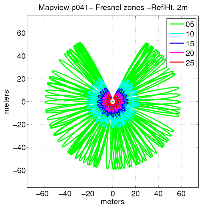
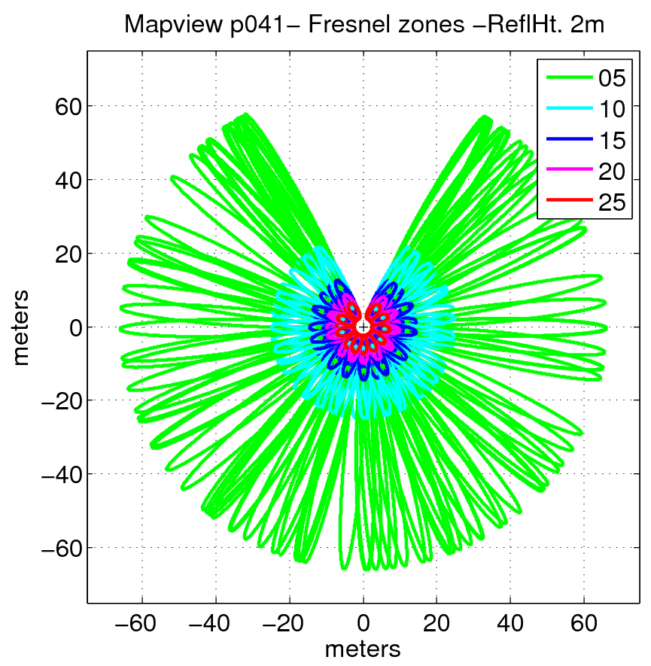
The equations you need for a Fresnel zone are given in the appendix for Larson and Nievinski (2013). Here are static examples for a 2 meter reflector height for L1 and L2.
L1 |
L2 |
|---|---|
|
|
Compare with a 25 meter reflector height:
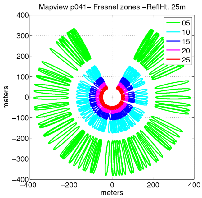
25m reflector height Fresnel zone
Similarly, the sampling rate you need to use is not unknown – you just need to understand how the Nyquist frequency is defined for the SNR observations.
Designing a good GNSS Reflections Site:
Sampling interval should be commensurate with your reflection target area. You can generally get away with 30 sec for surfaces that are < 10 meters below the antenna, but I urge you to use 15 sec. For reflectors larger than 50 meters, I recommend 1 sec sampling. The bare minimum sampling rate numbers you need can be calculated using the code in Roesler and Larson (2018). This code can also be run from the GNSS-IR web app
Make sure your antenna is surrounded by natural planar surfaces. No crashing waves. No outlet glaciers. No large ships coming and going.
Use the reflection zone app or the python utility
refl_zonesto make sure that you can sense the surface you want to measure. This is extremely important for water levels, as many groups think seeing the water in a photo means you can measure it. All you need to check this is the position of your site. The app will calculate the geoid correction for the ellipsoidal height. If you are trying to measure an interior water body (where mean sea level is not relevant), there is a manual override.If you have flexibility, take into account that sites at mid-latitudes have holes in their sensing zone. In CONUS, don’t face your GNSS receiver to the north. In southern Africa, South America, and Australia, don’t try to use GNSS-IR to measure water levels to the south.
If you are trying to measure snow accumulation in polar regions, you should ensure that your antenna is always at least 1 meters above the highest snow level. This may mean you need to revisit your site to reset the pole vertically.
Operating a good GNSS reflections site:
Always remove the elevation mask on the receiver!
Set the sampling interval by evaluating reflection surfaces. The standard GNSS sampling interval of thirty seconds was selected over thirty years ago before the internet existed! Collect (and archive) more data.
Take photographs of your site.
If you plan to put your GNSS antenna on a roof, pick the corner that gives you the best view of natural surfaces.
Track all GPS signals! (L1 and L1C, L2P and L2C, L5). If you can track GLONASS, Galileo, Beidou without costing a lot of money, I strongly recommend it.
It doesn’t matter if you turn on multipath suppression algorithms or buy a fancy antenna. They don’t stop multipath.
Put SNR data in your RINEX file. RINEX 3 is generally preferred because it makes it easy to include all signals, but RINEX 2.11 is fine as long as you make sure the file has L2C and L5 in it.